They kicked GOD out of our schools.
Guess who they replaced Him with?
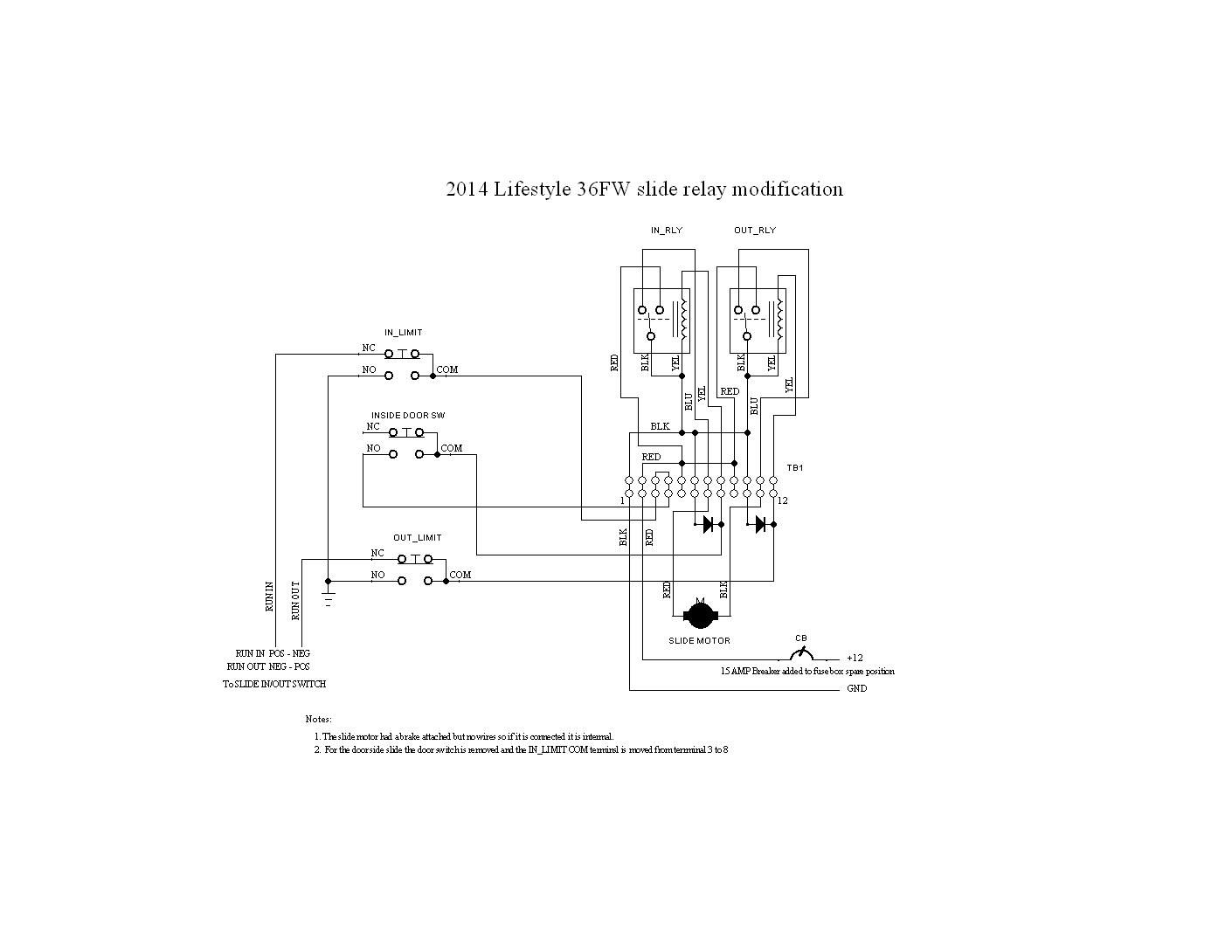
CARRIAGE/LIFESTYLE FULL WALL SLIDE RELAY MOD
NOTES:
1. The reason for the addition of relays is to reduce the amount of current that flows through the limit switches. The limit switches used are rated
for 15 amps AC but only 1/2 amp DC. The motors run off DC and are rated as 15 amps DC so the switches are not rated to handle the motor current.
The way our unit came from the factory, the limit switches were wired so that the full motor current passed through them. After a number of uses,
arcing in the switch because of the high current will burn the contacts and cause them to become resistive. This causes the motor to
run slow or not at all.
2. The wire used in our unit is #10 wire which can handle up to 30 amps DC depending on its length. There was no need to replace the wire. By adding the
relays you are removing the limit switches and a long run of wire from the motor circuit. The limit switches now only have to handle the current needed to
activate the relays which is within the 1/2 amp DC rating. I did replace the limit switches as the originals were damaged.
3. The door-side and full-wall relay mod are wired the same except for the door switch. In the door-side wiring the terminals used for the door switch are
jumpered togather. The wiring on the full-wall side will allow the slide to run out with the door open but will not let it run in. Running out with
the door open is not a problem. I started to add another door switch to the bathroom door but haven't. The bathroom door being open when the slide is
run in can be a problem. On the door-side I used the original 12 volt source. On the full-wall side I added a 15 amp automotive breaker and ran seperate 12 volt
and ground wires (#10) from the fuse box.
4. I wired the relays on a piece of 1/16 inch sheet metal that came from Lowes. I don't like to mount components that can get hot to wooden surfaces. I
also like to use barrier terminal strips as tie points. It makes the wiring easier to troubleshoot. It is also much easier to wire it on the workbench. I screwed the
relay panels to a floor joist near the motor on both slides. The relays I used are 12 volt automotive type relays rated for 40/50 amps. The relay sockets
came with the relays. The limit switch replacements were of identical type and rating. The diodes used on the relays are there to short the reverse voltage
generated by the relay when it is released. They are general purpose diodes rated at 1 amp 100 volts. All of the parts I used were purchased on Ebay with the
exception of the 15 amp breaker that can be had at any local automotive supply.
5. I adjusted the door-side limit actuators to stop the slide in the correct place. When it came from the factory it had
never been adjusted and the lock nuts on them had never been tightened.